

Key Project Summaries
Characterizing the Response of a 1923 Suspension Bridge
 Situation: A Northeastern toll bridge owner operates a 2,200’ suspension bridge over a major river. Due to diligent bridge management over the life of the structure, the bridge is in very good condition. However, recent inspections by a third party identified several anomalies that were concerning, including a crack on one cable anchor. The owner was referred to LifeSpan by his third party inspection engineer.
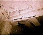
Installation: After consultation among the owner, third party engineer, and LifeSpan Technologies; a design was developed and a turnkey contract let to install a monitoring system that would help characterize the nature and severity of the anomalies noted during inspection. LifeSpan, through its installation contractor, installed model TA sensors to capture strain data on two tower legs, redundant bidirectional inclinometers on the top of one tower, and model TA sensors over an anchor crack to monitor crack width changes with temperature or propagation. The installation was planned for five days, but was completed in three days, with no technical or contractual issues.
Discussion: After twelve months of continuous operation, the monitoring system has continued to perform well. Tower inclination has been seasonal. While the captured strain values are influenced by temperature changes, the magnitude of the non-temperature induced strain values are well within reasonable levels. Monitoring is expected to extend for several years with structural analysis to follow.
Verifying the Load Capacity of a 1938 Dam Bridge
 Situation: A resort lake in the southern United States has a narrow two lane road fabricated over a seventy year old dam that has been severely load restricted as a result of visual inspection. The owner desires to widen the roadway to improve safety and strengthen the superstructure members to allow legal highway loads across the dam. A local consultant was hired to provide a unique design that widened the roadway and strengthened the superstructure. A state DOT engineer recommended that the bridge owner contact LifeSpan to determine if project construction costs could be minimized from a more objective, precise assessment of existing structural integrity.
Installation: A standard LifeSpan automatic monitoring system was used for static load testing in three locations, then remained in the third location for long term monitoring. Access for sensor placement from the roadway was virtually impossible using a bucket truck, which would have also required days of closure of the roadway. Instead, installation was accomplished by using a telescopic boom lift, providing a safe work platform approximately 150 feet above the base of the dam. Despite an unexpected 15F cold snap, the installation was completed two days ahead of schedule and on-budget.
Discussion: Static load testing was performed at all three locations using LifeSpan’s Internet portal functionality. Traffic flow was virtually unimpeded because of the rapid data capture. It is anticipated that the results from the load tests and long term monitoring will significantly reduce overall construction costs.
Comprehensive Monitoring System for a New Signature Cable Stay Bridge
 Situation: In 2013, the New York New Jersey Port Authority (NYNJPA) elected to construct a major new bridge alongside the alignment of the existing Goethals Bridge, connecting New Jersey and Staten Island. The old Goethals Bridge, completed in 1928, was woefully undersized for today’s traffic demands. The NYNJPA requested proposals from several major engineering/construction consortia and selected a well qualified team to build two cable-stayed crossings. Parsons Transportation was the engineer of record for the Kiewit-Weeks-Massman AJV. Parsons selected LifeSpan Technologies to design and specify the structural monitoring system.
System Design: The NYNJPA elected to install a variety of instrumentation at various locations on the bridge towers and road deck. A unique system was designed to capture movement of the expansion joints that are necessary to accommodate thermally induced displacements of the road deck. A high speed network transmitted all data to a centrally located data historian server.
Discussion: While structural monitoring is generally utilized to safely extend the life of existing bridges, the monitoring of signature bridges is uniquely different. LifeSpan configured the sensor hardware, designed the entire data historian functionality, and made vendor recommendations; fully aware that the purpose of this system was to identify structural response patterns, supporting optimized operational and maintenance well into the future.
Structural Monitoring of a 1926 Strauss Trunnion Bascule Bridge
 Situation: A state DOT was concerned about the condition of their Strauss trunnion bascule bridge. The leaf structural members were sufficiently worn to make infrequent opening and closing difficult. In addition, the approach road surfaces were not well adjusted for height, allowing cars and trucks to place additional impact loading on each leaf. The owner determined that visual inspection was not capable of revealing the actual condition of the structure. Consequently, the owner decided to install a LifeSpan real-time structural monitoring system to ascertain actual live load effects and to determine how long a replacement structure could safely be deferred.
Installation Summary: Heavy traffic on the bridge precluded standard installation procedures. The owner arranged for a specialized boat with a bucket extension that could precisely control its position under the bridge as the platform for installation of thirty sensors – fifteen on each leaf. Both LifeSpan’s PeakStrain™ TA (peak tension & active) and CA (peak compression & active) sensors were installed at locations where the owner calculated that the live load strains would support a decision about structural integrity. All sensor cables were installed in flexible conduit to protect against damage.
Discussion: It was immediately obvious from the commencement of monitoring that the mismatched road surfaces were a significant contributor to higher than expected strain values. An objective determination of structural integrity and actionable decisions will be made during the full thermal cycle monitoring.
Global Health Monitoring for a 1959 Swing Bridge
 Situation: A mid-twentieth century swing bridge in the United States was modified by the addition of a sidewalk on one side of the bridge. Counterweights were eventually installed on the opposite side to balance the load, but concerns were raised about the overall ability of the structure to accommodate this additional weight, especially the ends of the movable section. The owner decided that a comprehensive, real-time structural monitoring program was needed to assure safe operations and potentially delay any additional structural modifications. A LifeSpan remote monitoring system with sensors on both sides of the bridge was installed to capture both strain and temperature data for analysis of the global structural integrity.
Installation Summary: Fourteen LifeSpan sensors were installed on the bridge in matched pairs. All three configurations of LifeSpan’s patented PeakStrain™ sensors were used — model TA (peak tension & active); model CA (peak compression & active) and model TC (dual peak in both tension and compression displacements). The installation was conducted during overnight hours to minimize the impact on car traffic.
Discussion: Data will be collected for several months before determining the overall structural integrity of this swing bridge and its ability to continue safe operations. It is expected the owner will continue monitoring this structure for many years.
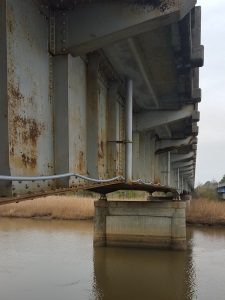
Keeping a 1963 Concrete Bridge Safe during Construction of its Replacement
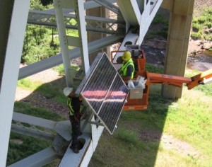
 Situation: A state DOT decided to replace a two lane, 50+ year old, 2.7 mile long concrete coastal bridge that was assessed to be in poor condition and subject to significant scour due to strong tidal forces. In 2013, the bridge was temporarily closed as a result of scour. During the construction of its replacement, the older bridge was required to remain in service for the normal tourist traffic, and also for periodic heavy construction loads imposed by trucks hauling pre-stressed beams for the new bridge. If the old bridge was incapable of handling these heavy loads, the cost to build the new bridge would be substantially higher.
Installation Summary: The state DOT hired a highly experienced engineering consultant to work with LifeSpan to formulate a realistic monitoring approach to understand the impact of heavy loading, and also to ensure safety for all users. As a result of our collaboration, the consultant decided to install two monitoring systems at different locations: (a) a manual monitoring system consisting of twelve Dual Channel PeakStrain™ sensors, and (b) a fully automatic monitoring system consisting of 24 Dual Channel PeakStrain™ sensors, three temperature sensors, and four inclinometers to capture data related to potential scour issues. The installation, as is typical for LifeSpan, was completed on time and on budget with no technical or contractual issues.
Discussion: Not long after installation, the monitoring systems were subjected to the full fury of Hurricane Matthew with winds of 100+ mph and storm surge tides. During the ensuing years, four more major storms battered the area around this bridge. The LifeSpan monitoring system, powered by solar array and batteries, remained fully operational during these significant events, capturing and transmitting all structural data as planned without interruption. These systems will remain in place until the new bridge is open, then moved to another problematic bridge in the state, lowering the per use costs for the owner.
Crack Monitoring on a 1973 Curved Girder Box Beam Bridge
 Situation: A curved girder, post-tensioned, box beam bridge over a United States Interstate highway had long, visible interior concrete shear cracks in multiple sections, as noted from several visual inspection cycles. The cracks appeared to be propagating over time, but could not be objectively confirmed using only visual inspection. LifeSpan’s structural monitoring technology was deployed to assist in determining the root cause of the cracking. Depending upon the severity of crack width changes and nearby strain values, the owner could potentially (a) initiate a replacement project, (b) develop a repair methodology, or (c) safely defer both options if the crack width data was shown to be stable. LifeSpan’s patented PeakStrain™ sensor is ideal for objectively determining crack displacements and can hold peak crack width values without power, reducing the data necessary for subsequent analysis.
Installation Summary: The owner purchased a LifeSpan automatic monitoring system which included ten PeakStrain™ sensors, three temperature sensors, a cellular based controller and a battery/solar panel power unit. The installation was conducted inside the box beam girders with personnel and equipment access through a hatch. Three displacement sensors were mounted over the largest interior cracks and seven sensors were mounted at horizontal locations just above the floor and below the ceiling. All required work was completed on-time and on-budget. The pre-made cable runs were oversized, allowing the owner to move each PeakStrain™ sensor up to 250 feet in any direction from the cable entry if new locations were determined to be essential for diagnosis. This flexibility is the essence of LifeSpan’s Progressive Diagnostic Protocol.
Discussion: Data is being collected and provided to the owner via Lifespan’s Internet accessible web site. It is expected that the owner will use the captured data to help determine the root cause of the cracking. For example, if the crack width changes are related to high strain levels, the cause could be (a) heavier than expected trucks using the overpass or (b) potentially a loss of pre-tensioning – a more serious problem. The owner is confident that LifeSpan’s structural monitoring technology will support an objective and timely decision, making the best use of limited government funding.
Load Capacity and Proper Bearing Operation on a 1956 Strategic Route Bridge
 Situation: The load capacity of a mid-twentieth century bridge adjacent to a United States hydroelectric dam was of concern to the owner. Nearby bridges over this river were programmed for extended repair closures. With the knowledge that this bridge would become the future mission critical route for detoured trucks, the owner determined that a LifeSpan structural monitoring system would provide the necessary information to confirm that the bridge had sufficient live load capacity when the detours were implemented. In addition, the bridge bearings were visibly out of place and possibly frozen. If the bridge experienced significantly increased live loads as a result of the detour, the bearings could fail which would lead to failure of the bridge deck.
Installation Summary: Twelve Internet accessible LifeSpan PeakStrain™ TA (peak tension & active) and CA (peak compression & active) sensors and four inclinometers were installed at key locations on this bridge using battery/solar as a power source. The installation team utilized a platform lift with minor traffic disruption.
Discussion: While early in the long term monitoring period, the reported strain values confirm that the bridge has adequate reserve load capacity for the programmed detour. In addition, the data also details that three of four bearings are frozen and the fourth has limited movement. And while additional data needs to be captured to conduct a definitive analysis, the LifeSpan real-time monitoring system is performing as specified and providing precisely what the owner desired.
Safely Extending the Asset Life of a 1948 Fracture Critical Bridge
 Situation: The second of two fracture critical southbound highway bridges over a United States river was a growing concern for the owner. This bridge exhibited visual signs of deterioration, particularly section loss. The mirror bridge, on the northern branch of the river, has been carefully monitored by LifeSpan for seven years. Actionable data from the northern bridge proved to the owner that its replacement could continue to be safely deferred. Each year of deferral is worth approximately $2.5 million dollars to the owner. As a result of the success of the northern bridge monitoring, the owner decided to also install a similar LifeSpan real-time structural monitoring system on the southern bridge to evaluate safely deferring its replacement.
Installation Summary: Eighteen LifeSpan PeakStrain™ TA (peak tension & active) and CA (peak compression & active) sensors were installed at strategic locations, along with a battery/solar power system. Three temperature sensors were placed for statistical analysis after completion of a thermal cycle. The entire installation was accomplished using a platform lift and completed quickly, with minimum traffic disruption.
Discussion: Initial strain values were not surprising and reasonably similar to the northern bridge’s historical data. Additional strain and temperature data will continue to be captured, allowing a structural analysis to be conducted by the owner. Assuming this bridge can safely carry highway loads and infrequent permit loads, the owner will continue to monitor this bridge for safety assurance, knowing that increasing strain levels over time with approximately the same live loads is an indication of ongoing deterioration that must be carefully monitored.
Crack Monitoring on Twin 1974 Interstate Overpass Bridges
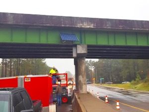 Situation: Adjacent Interstate overpass bridges had visible cracking noted on several NBIS inspections despite installation of a mid-span pier. Visual observation and periodic inspections were insufficient to determine the crack propagation and the root cause. To understand how potentially overloaded trucks may be impacting the localized strains that generated these cracks, the owner decided to install a modest LifeSpan crack monitoring system. The ability of a real-time, Internet based structural monitoring system to rapidly assess crack width changes, the effects of live load on those changes, and the ability to alert the owner when significant crack changes occur are the principal reasons why the owner chose to install LifeSpan systems.
Installation Summary: Six LifeSpan PeakStrain™ TA (peak tension & active) sensors were installed at two locations on each bridge. Two sensors were placed slightly ahead of close proximity cracks to measure crack propagation and third TA sensor was installed at a nearby location so that the live load strains can be captured. In addition, temperature sensors were installed for additional analysis. The installation was performed from a platform lift with zero disruptions.
Discussion: During the first week of monitoring, one of the sensors captured significant active crack propagation, even though the change in crack width was not visible by the human eye. All sensors have reported crack movement. Monitoring at these bridges will continue until the crack activity generated by live loads is fully understood, corrective action taken, and the repairs have been verified as successful. Once completed, the LifeSpan monitoring systems will be relocated to other bridges in the owner’s system.
Railroad Owner Saves $2M+ and Increases Train Speed
 Situation: A regional railroad owner was concerned about load ratings for a deck girder bridge that is 100+ years old with self-imposed train speed limits of 5 MPH. An analysis and report by a local engineering firm, using only visual inspection and theoretical strains, recommended that a significant number of members on the bridge would need to be replaced so that expected loads could be carried safely in compliance with FRA bridge management regulations. After recognizing the implications of those recommendations for reduced loads and cost, a national engineering firm was engaged to provide a more in-depth evaluation of bridge performance using a sensor kit provided by LifeSpan Technologies.
Installation: LifeSpan Technologies’ Sensor Kit, consisting of dual channel PeakStrain™ sensors and hand held reader, was employed for a two day managed load test conducted by the national engineering firm. Tests using known train configurations were performed at varying loads and speeds to characterize the stress on certain bridge members. Because the LifeSpan sensors do not require power or wiring to a data collection unit to obtain maximum or peak strain, the test setup was rapid and very affordable for the railroad owner.
Discussion: Analysis of the strain data indicated that while the bridge is experiencing significant stress, it is safe to operate as-is under AREMA guidelines; saving the owner over $2 million dollars in structural refurbishment costs. This objective load test also identified bearings that should be repaired or replaced, and suggested that the owner may be able to increase train speed (a big plus) well above the self-imposed 5 MPH speed limits.
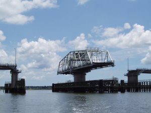
Safely Extending Asset Life of a 1902 Swing Bridge
 Situation: A complex, early 20th century, multi-span truss bridge with one swing span crossing a navigable North American waterway was causing concern for the owner. After visual inspection confirmed what appeared to be section loss, the structure was scheduled for replacement, pending approvals and funding. Because near-term funding remained problematic; the owner decided an objective, precise assessment of current condition was essential to support safe operations and optimize the bridge’s required, extended life span.
System Installation: As a result of the complex structural interactions on the bridge, the owner and third party engineers decided to install a broad array of sensing devices to accurately and objectively determine its current condition. Devices included tilt meters, accelerometers, temperature sensors; plus twenty LifeSpan Dual Channel PeakStrain™ sensors, both peak tension and peak compression. Since wiring between the fixed span and swing span was physically impossible, two independent electronics units communicating via WiFi were installed. Bridge data is available on-demand for both the owner and engineers over a secure, cloud-based Internet portal.
Discussion: The performance data collected permits the structural engineer to ascertain member load distributions and assess whether the members are operating within acceptable working stress ranges. Knowledge of the actual strain values will also allow the structural engineer to build and calibrate a finite element model (FEM) for the structure. A calibrated FEM will enable the owner to (1) identify potential problems to drive guided visual inspections such as crack initiation locations; and (2) verify if load restrictions can be lifted. Finally, continuous monitoring will enhance safety during the final years of this structure’s useful life.
Structural Monitoring Technology for Management of a Pin & Hanger Bridge
 Situation: A state DOT decided to incorporate the benefits of structural monitoring technology with their evolving asset management plan. The owner surmised that the current visual condition assessment process may not be sufficiently objective and accurate, especially for distressed structures, leading to repairs or replacements that are not absolutely essential. The owner believes the judicious use of this technology will support difficult bridge management financial decisions.
Quoting from the owner’s press release about this project: “If it proves successful, we’ll install these sensors on other structures throughout the state, allowing us to monitor a variety of characteristics, such as load capacity and bridge movement, which will enhance everything that we’re already doing as part of our inspection program.”
System Installation: Working with the owner and a third party engineering consultant, LifeSpan delivered a solution for this pin & hanger bridge consisting of PeakStrain™ and temperature sensors, a rugged controller and a battery/solar array system that will provide uninterrupted power for years. The structural monitoring system was installed in less than four days with minimal disruption of traffic. After completion of this project, the system will be moved to another bridge.
Discussion: The consultant and owner were trained on the unique system features, incorporating both the capture and display of relevant data. A static load test was performed by the consultant to ascertain proper load ratings and response of the structure to a controlled live load. A calibrated finite element model will also be developed. The installed system has demonstrated that seasonal temperature change, not live load, is the key driver for observed changes in strain levels.
Crack Monitoring for a 1957 Signature Suspension Bridge
 Situation: A signature suspension bridge in North America experienced minor steel cracking directly under several upper floor beam flanges. This cracking is anticipated to be related to out-of-plane bending. It is essential to determine the cause, so that a repair methodology can be developed, installed and verified. The owner’s consulting engineer knew that LifeSpan’s unique PeakStrain™ sensor would be ideal for objectively determining minute displacements of the steel and retaining those peak values without power. A manual monitoring system was selected as the most cost effective method of (1) confirming the cause of the cracking, and (2) confirming that the repair method successfully eliminated or reduced the out-of-plane bending.
System Installation: The owner’s consulting engineer arranged for the purchase of a LifeSpan Sensor Kit, which includes ten PeakStrain™ sensors and a hand held reader. LifeSpan conducted a training program at the bridge site. Several engineers and maintenance personnel attended the program. LifeSpan covered the theory and implementation of high precision sensors to capture objective data, and the use of the data to analyze structural behavior. Particularly effective was the hands-on training that the maintenance staff received, both in the maintenance shop and on the bridge. This allows the staff to install, capture data, remove and adjust as necessary, sensor locations for ongoing data collection.
Discussion: Data is being collected in two locations. It is expected that the owner’s consulting engineer will use the captured data to confirm his initial diagnosis of why cracks are forming. A preliminary repair program has been discussed and will be implemented after the final diagnosis. The owner will likely extend the monitoring program to other locations where out-of-plane bending is also expected, simply to implement a planned maintenance program before more cracks appear. Especially for signature structures, it’s always better to anticipate potential problems than to react after the problems are uncovered, resulting in unplanned traffic disruption and significantly added expense.
Crack Monitoring for a Signature Tunnel Structure
 Situation: A signature tunnel in North America experienced concrete cracking sufficient to concern the infrastructure owner. The owner’s consulting engineers contacted LifeSpan to discuss monitoring the crack behavior, expansion and propagation at side wall and ceiling locations. Collection of precise, objective displacement data was determined to be the most efficient and cost effective method to analyze the structure’s condition. A manual data collection system was chosen, with provisions for upgrading to a LifeSpan automatic, cloud-based monitoring system.
System Installation: Thirty-five LifeSpan Dual Channel PeakStrain™ sensors were installed over cracks in both the side chambers and at selected ceiling locations. Work was performed over several evenings using portable lifts during tunnel closures for the safety of the installation crew. Cable runs from the ceiling sensors were placed in secure rigid conduit and terminated into junction boxes for ease of manual data collection. Along with training, initial sensor readings were taken with the owner’s consulting engineers before demobilization. LifeSpan continues to provide post-installation follow-up and support.
Discussion: Using the Progressive Diagnostic Protocol developed by LifeSpan Technologies, the tunnel owner now relies on financially efficient, precision equipment to monitor this mission critical asset. Additional sensors can easily be added upon recommendation by the owner’s consulting engineers. Conversion to an automatic, cloud-based system can be implemented rapidly and at a reasonable investment cost.
Characterizing the Response of a Signature Cable-Stayed Bridge
 Situation: A Southeastern state DOT elected to conduct in-depth monitoring to characterize the structural response of its most valuable bridge. The bridge, a six year old cable-stayed design, is subject to several major non-live load forces — seismic, wind, and thermal. Increased knowledge of the structural response will lead to better decision making for non-routine maintenance, inspection effectiveness, and maximizing asset life.
System Installation: The owner decided that LifeSpan’s Progressive Diagnostic Protocol approach would best meet its needs. While both system controllers were sized to accommodate a future doubling of sensing devices, only 24 PeakStrain™ and six temperature sensors were initially installed, providing the owner with a reasonable and cost effective starting point for understanding the structural response. Of particular interest are peak strain values, both tensile and compressive, in major floor beams, stay girders and two cable stays. The project was delivered on-schedule and on-budget.
Discussion: The owner frequently checks the values returned via the cellular network to the network operations center from his iPad. While the expected live load strains are relatively minor, the entire bridge system is experiencing significant thermal loading. The data will be reviewed over time to quantify the actual effects of temperature change on the structure and additionally, the operation of the expansion joints. Monitoring is ongoing and expected to last for years. Additional sensing devices may be added at key locations as initial diagnostic conclusions are made at the end of the first thermal cycle.
Reducing Bridge Postings with Maximum Strain Data
 Situation: Load postings on bridges increase commercial user costs by higher fuel use and lower driver productivity. Postings affect other bridges and local residents with collateral damage, congestion and increased air pollution. A state DOT recently decided to implement an AASHTO-approved alternative process to calculate more accurate and hopefully less severe load postings as a means to enhance local economic competitiveness and spur economic development, while reducing the negative effects caused by detours.
The Process: The 2011 version of AASHTO’s Manual for Bridge Evaluation (MBE) states: “The actual performance of most bridges is more favorable than conventional theory dictates. When a structure’s computed theoretical safe load capacity or remaining fatigue life is less than desirable, it may be beneficial to the Bridge Owner to take advantage of some of the bridge’s inherent extra capacity that may have been ignored in conventional calculations.”The MBE explains how to use maximum strain values obtained from sensors to calculate a correction factor that can substantially increase the safe load rating.
Discussion: The state DOT has supplied sensor kits to each bridge inspection team as an additional tool to capture not only maximum strain for load posting calculations, but also field monitoring of cracks, load distribution studies, out-of-plane bending, and proper operation of bridge bearings. The expectation is that the bridge inspection personnel will be more closely aligned with engineering and maintenance objectives, supporting difficult decisions on load postings, rehab or replacement actions. Fifty percent of bridges evaluated so far have avoided a restrictive load posting.
Confirmation of a Unique Repair Methodology for Concrete Bridges
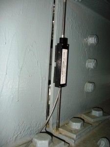
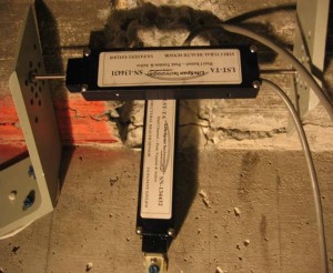 Situation: A state DOT was experiencing concrete cracking between superstructure beams and deck on a number of bridges across the state. Although the beam-deck joint was assumed to be integral, undetermined forces were causing the deck to move horizontally and vertically, creating cracks along a fillet and shearing reinforcement bars. After several expensive bridge replacements, the DOT decided to try a new repair methodology to reduce the expense and outage time from wholesale replacement of these deficient structures.
System Installation: The state DOT decided to install sixteen dual channel PeakStrain™ sensors at various locations across existing cracks in a manual data capture configuration. As the photograph shows, some sensors were installed at right angles to capture both horizontal and vertical displacement at the same location. The installation was accomplished at night, to avoid traffic issues; and was completed safely, on-schedule and on-budget.
Discussion: LifeSpan worked with the state DOT to develop a data capture scheme to determine the effectiveness of the proposed repair. This cost-effective manual solution was possible because LifeSpan PeakStrain™ sensor can capture maximum displacement without power. The state DOT used a LifeSpan handheld reader to determine maximum displacements before the repairs started and again, after repairs were completed –comparing the displacements to confirm that the unexpected lateral and vertical movement had stopped. LifeSpan’s sensors confirmed the repair technique; saving this state DOT millions of dollars in unnecessary bridge replacements.
Safe Extension of the Operating Life for Two Structurally Deficient Bridges
 Situation: A state DOT was concerned about two long-span bridges that showed degradation due to heavy section loss from age and in one case, tidal salt water. Both bridges were eligible for replacement due to low sufficiency ratings, but only one was possible to replace due to funding constraints. Heavy truck traffic required consideration of structural strengthening for one bridge being replaced while the new bridge was under construction. It was determined to defer the $875,000 project in favor of monitoring to assure safe operations. The owner decided to monitor the other structure also for assurance of safety while a replacement project was deferred in favor of higher priority projects; a fundamental tenant of good transportation asset management.
System Installation: LifeSpan installed less than twenty of its PeakStrain™ sensors at various locations on each bridge. Sensor locations were selected by the bridge owner to capture strain at periods of maximum and minimum loading, for both tension and compression members. Because of their unique design, LifeSpan’s PeakStrain™ sensors are capable of capturing peak strain events even without power, so important data is not missed. Several temperature sensors were also installed to determine the influence of temperature on observed strains. A system controller and solar power source were part of the solution for each bridge. Installation was completed on-schedule and on-budget.
Discussion: The state DOT periodically reviews information in graphical format on smartphones and personal computers over the Internet via LifeSpan’s network operations center (NOC). The NOC is completely secure and password protected, allowing only the state DOT to access the structural information. Changes in the performance of one bridge led the DOT’s enforcement unit to apprehend overloaded logging trucks illegally using the bridge. In addition to assuring safety, this state DOT sees a robust return on investment as replacement capital expenditures are deferred.
Confirmation of a CFRP Repair Methodology for Concrete Bridges
 Situation: A major U.S. city was faced with replacing fifteen short span bridges to upgrade their load carrying capacity. Because of unique design standards required by a channel crossing, replacement bridges were estimated to cost about four million dollars each; a total of $60 million for the entire replacement program. Just prior to signing a contract for the first bridge replacement, a national engineering firm contacted LifeSpan to see if we could monitor structural response after installation of a CFRP (carbon fiber) strengthening solution. The system needed to be installed before rising water in the channel made access to the structure impossible. LifeSpan delivered and installed the custom configured system ahead of schedule, less than thirty days after receipt of the order on Christmas Eve.
System Installation: LifeSpan worked with the engineering firm to install a comprehensive solution, consisting of nineteen dual channel PeakStrain™ sensors, four temperature sensors, and an on-site controller for data capture and communication with LifeSpan’s Internet Network Operations Center. The controller was powered by a battery pack with solar recharge installed on a concrete pad near the bridge. To protect against vandalism all wiring was installed in conduit, with chain link fencing and razor wire surrounding the equipment cabinets.
Discussion: The most interesting facet of the LifeSpan solution was the embedment of four sensors in the deck, with two sensors mounted on top of the CFRP rods that were buried in the concrete. The engineering objective was to measure load induced strains and compare strains on the CFRP rods with strains in the concrete deck. Also, a series of sensors were installed underneath the deck, some mounted on CFRP soffit mats and the remainder on the concrete soffit. The system returned data flawlessly for several years. The city is projecting savings of nearly $45 million dollars by using this repair technology while confirming repair effectiveness with a LifeSpan monitoring solution. The project received the prestigious Engineering Excellence Grand Award from the state’s ACEC.
Out-of-Plane Bending on a Signature Suspension Bridge
 Situation: A national engineering firm needed to assess the impact of fatigue cracking, severe section loss, and potential out-of-plane bending on a series of stringer webs on a signature suspension bridge. They contacted LifeSpan Technologies and discussed how such monitoring could be implemented. In particular, the bridge owner was concerned about future limitations of loads due to continued degradation of this signature bridge and had a seventy million dollar repair project ready to remediate this problem.
System Installation: LifeSpan installed eighteen dual channel PeakStrain™ sensors at locations chosen by the owner’s engineering consulting firm. In particular, LifeSpan’s unique sensors were mounted to capture web deflection in both tensile and compressive modes. The installation of LifeSpan’s sensors was accomplished on-schedule and on-budget.
Discussion: LifeSpan’s PeakStrain™ sensor is extremely versatile, allowing measurement of a wide range of variables under demanding conditions. In this project, mounting was by means of customized extension rods installed on both sides of the stringer flanges. Stiffness of these rods had to be assured, which was accomplished by use of a novel backer magnet that prevented bending toward the web. The LifeSpan solution continues to report data with no interruption of peak displacement capture even with intermittent power loss by the third-party systems integrator’s data capture electronics. The ability to capture peak data without power was a major factor in deciding to use LifeSpan’s PeakStrain™ sensor. And, the owner has successfully deferred implementation of the seventy million dollar repair project, saving well over three million dollars in interest cost every year.
Load Monitoring for a Major Retailer
 Situation: A major U.S. retailer built a new store with two levels; one for their traditional format, the other for a warehouse format. The load carrying capacity of the second floor beams was questioned before completion, since point loading was expected, given the inevitable movement and concentration of palletized inventory.
System Installation: A forty channel LifeSpan strain sensor monitoring system was installed with appropriate control hardware and software. Displacement data was captured on a regular schedule and data uploaded to LifeSpan’s Network Operations Center (NOC). A local overload annunciator panel was also installed and activated for alerting in-store personnel. The project was delivered on-budget and within thirty days of receipt of order (two weeks ahead of schedule).
Discussion: The owner was concerned about controlling point loading to avoid high levels of stress/strain on the second floor beams. Internet capture and distribution of the sensor derived information was made available to store personnel, the building contractor and structural engineers. The sensor information clearly showed store loading (initial inventory build) and subsequent additional loading in certain areas prior to the Christmas holiday season. After reviewing the information captured for six months, the structural engineering firm established limits of displacement/strain and these limits were programmed into the local alarm software. Store personnel received alarms when loading was over established limits and took corrective action to alleviate potential overloaded conditions. This solution saved the owner millions of dollars in unnecessary repair work and a substantial delay in the store opening.
Effectiveness of the Repair Program for an Older Deck Truss Turnpike Bridge
 Situation An Eastern toll authority developed plans to repair an older deck truss bridge structure on their system. Prior to letting the repair contract, the authority decided to install a structural monitoring system that would monitor key compressive and tensile stresses for up to six months, establishing a baseline of strains/stresses to compare against similar information captured after the repairs were completed. In essence, the owner wanted to determine if the recommended repair, based on an NBIS visual inspection, was necessary and effective.
System Installation: A twelve dual channel PeakStrain™ sensor monitoring system was installed with appropriate hardware and software, including a battery power source with solar recharge capability. Displacement/strain data was captured several times per day and relayed via cellular modem to LifeSpan’s Network Operations Center (NOC). Four sensors are measuring current and peak compression; eight are measuring current and peak tension. The installation was completed on-budget and ahead of schedule. Data flowed immediately to the owner.
Discussion: The owner has the ability to download captured data from the NOC into convenient Excel spreadsheets for subsequent analysis. The owner’s engineering consultant also noted differences in strain due to temperature differentials between a truss side exposed to the sun vs. the shade. Monitoring is ongoing and a finite element model was being developed using data from the structure, confirming the repair was not necessary. The system has been fully operational for approximately seven years on its original set of solar recharged batteries with no loss of data.
Damage from Adjacent Construction Activity
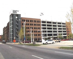 Situation: In addition to conducting condition assessment of older structures, LifeSpan’s configured solutions can be used to assure asset condition during adjacent construction operations. The City of Raleigh, North Carolina used a LifeSpan solution to assess the potential damage caused by adjacent deep excavation and foundation construction adjacent to their newly opened parking deck.
System Installation: Twenty dual channel PeakStrain™ sensors and a wireless monitoring system were installed. The LifeSpan sensor values were reported several times daily, during peak load and unloaded conditions. Alarm conditions were reported immediately. Uploaded to the LifeSpan Network Operations Center, the data was available for analysis at any time. The project was completed on-schedule and on-budget.
Discussion: If damage did occur, LifeSpan’s monitoring solution would automatically alert the City’s third party engineering firm. Their structural engineers could then evaluate the information, assess the damage, and work with the construction team to resolve any issues before the parking deck was damaged beyond repair. The cost of LifeSpan’s monitoring solution was a small investment to insure Raleigh’s new ten million dollar parking deck survived undamaged during adjacent construction.
CFRP Reinforced Concrete Structures
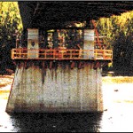 Situation: An older concrete bridge pier suffered severe corrosion damage. In some places, the corroded rebar expanded and cracked the overlying concrete creating a spalling condition. A composite, carbon-fiber wrap was applied to strengthen the pier and safely extend its life.
System Installation: A single, PeakStrain™ sensor was attached to the outside of each composite wrap to detect changes in hoop-strain. Since this was a manual system, no additional equipment, such as a power supply or data acquisition system, was required for this application.
Discussion: As the rebar continued to corrode and expand, it created hoop strain in the composite wrap. When this strain gets too large, it can damage the wrap, so that the composite wrap may not provide the additional strength required in this application. This condition can occur without any visible damage to the outside of the wrap as the column is now completely enclosed, and it is impossible to detect continued corrosion by visual inspection. Since the deterioration is quite slow, it is not necessary to monitor the sensors continuously. The inspector simply uses a LifeSpan handheld reader to capture data manually whenever he performs a routine inspection. The sensor provides a precise, quantitative indication of continued corrosion and warns of damage to the wrap that might otherwise go undetected.
Facade Cracks on the Washington Monument
 Situation: During renovation of the Washington Monument, a number of large facade cracks were discovered. These cracks penetrated through the stone veneer and extended vertically through multiple veneer stones. The cause of cracking was unknown and the US Park Service wanted assurance more severe cracking would not appear.
System Installation: An assortment of fifty sensing devices was installed to monitor crack width, temperature, tilt, humidity and wind force. Three groupings of sensors were located outside the Monument at approximately 200′ and 465′ above the ground. Additional sensors were mounted inside the monument at positions near those on the outside.
Discussion: Data from all sensing devices was collected every five minutes. The sensor controller transmitted this data once each day. The data was analyzed to correlate crack width with the other measured parameters in order to determine the probable cause of the cracking. The data was placed on a secure web site that incorporated a 3D model of the Monument, graphical data presentation and photographs of the sensors. Although the cracks did not pose an immediate structural concern, it was prudent to monitor to ensure that no additional remedial action was necessary.
Crack Monitoring of Steel Girders
 Situation: Large cracks were propagating in a steel girder bridge where the transverse cross-bracing attached to the girders. The owner needed assurance that stress relief measures were working.
System Installation: Several PeakStrain™ sensors were mounted between the girders and the cross-brace attachments. A data-acquisition system collected the outputs and transmitted the readings via cellular data modem to the owner’s offices.
Discussion: LifeSpan’s peak displacement sensor provides a precise record of how far the crack opens under varying traffic loads and temperature differentials. By monitoring the peak-displacement on a daily basis, it was possible to determine how quickly the cracks were growing
Differential Settlement of a Public Structure
 Situation: A large, public stadium needed to be expanded beyond its original size. The proposed new construction used mat foundations. The original construction was built on piles driven to bedrock. The stadium is in an alluvial, river basin within a zone-four earthquake area. Differential settling of the independent, reinforced concrete structure was considered possible and a potential problem if settling was not uniform.
System Installation: LifeSpan’s PeakStrain™ sensors were installed to monitor differential movement between the old and new stadium structures. Other sensors were installed to monitor acceleration of the upper decks and strain in several cantilevered beams. The sensors were located in three groups, linked to a central data collection location at the stadium. Combined data was transmitted to the owner via a telephone modem.
Discussion: This multi-purpose system collected data once a day to monitor the rate of differential settlement. This data was used to document structure settlement over time and to schedule modifications to utility connections before major damage occurred. PeakStrain™ sensors also captured peak displacements during events which stressed the structure, such as earthquakes and rock concerts.
Crack Monitoring in Concrete Box-Beams
 Situation: A large, concrete box-girder bridge used on a curved roadway was cracking as a result of torsional stress. Numerous surface cracks in the diaphragms inside the box girder were visible and extended around the entire diaphragm. Visual inspection was difficult and provided minimal detailed information on crack growth.
System Installation: A number of PeakStrain™ sensors were mounted across the largest cracks to monitor displacement as the cracks opened under traffic loads and differential temperatures. Cables were run inside the box girder to connect the sensors to a data acquisition system. Data was collected once per day for peak and current displacement.
Discussion: Increases in peak displacement under load are a direct and quantitative measure of crack propagation. Increases in crack width when thermal differentials are factored out can prove that irreversible damage has occurred and is progressing. Data was collected and reported each day and trends plotted to determine if remedial action was necessary.
Monitoring Shipping Damage
 Situation: Bulb-T, pre-stressed concrete beams were to be used for construction of a new bridge. Previous beams of this type exhibited large surface cracks in the girder and some of the girders were noticeably damaged during shipping to the construction site.
System Installation: A single PeakStrain™ sensor was mounted on the girder at mid-span to ascertain maximum strain experienced during shipment.
Discussion: After the girder arrived at the bridge site, the sensor was connected to a hand-held device to display the peak-strain it experienced during shipment. In applications like this, the sensor can be left in place after installation and checked manually during regular bridge inspections. Depending upon the cost of inspection and data frequency required, these sensors can also be connected at a later date to LifeSpan’s controller for remote, near real time monitoring.